REU: Computational Imaging
5 min read
TLDR
(click to show/hide)
For my first undergraduate research experience I worked remotely during the pandemic at Harvey Mudd College.
The focus was computational imaging; using computers to aid in high-resolution / non-tradional photography. My partner and I
made a 3D-printed microscope that could take several low-resolution pictures and 'stich' them together to make a high-resolution
output image.
In the summer after my sophomore year, I attended a data science REU
through Harvey Mudd College. This was quite a broad topic so
individual groups main goals varied. In my particular group with
Josh Brake, we worked on
Biophotonics in three subgroups. This was my first introduction to the
field on Computational Imaging and found myself fascinated by how
widely used it is in modern technology. We looked at examples of
telescopes, MRI machines, and phone cameras to scratch the surface
before diving into the specific innerworkings of the techniques we
would study and attempt to implement.
Through this article, I plan to recount some of the most interesting
topics we worked on as well as include some technical information on
pieces of the project I knew particulary well. My subgroup of two
worked on UC2 Fourier Ptychographic Microscopy so I will explain some
of the design concepts of our UC2 system as well as the idea behind
the FPM algorithm.
What is Computational Imaging?
In essence, computational imaging is the design and implementation of
algorithms which uses data to reconstruct and image what a traditional
imaging system would not be able to take. Examples of this include CT
scans which combine multiple X-Ray images into a single three
dimensional image, deep space imaging which can involve recovering
information from sparse data and unblurring images, and more advanced
systems such as seeing around corners or even directly through highly
diffuse materials.
What is UC2?
Relatively recently, an article was
published in Nature proposing a new standard for experimental imaging
setups. The idea is to provide open-source 3D printing files for
various optical building blocks. These are intended to simplify the
construction of complicated microscopes for lab use and drastically
decrease the costs of some of the more expensive parts.
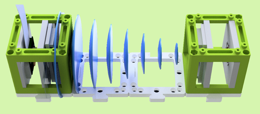
In-line holography setup using UC2 modules
When our REU began, UC2 had just begun a few months prior, so not many
setup plans and tutorials had been created in their
GitHub
repository. Our plan was to learn about Fourier Ptychographic
Microscopy setups and then add relevant details to the repo. Hopefully
we would be able to contribute some new modules as well as physically
print and build our setup.
What is Fourier Ptychographic Microscopy?
Fourier Ptychographic Microscopy (FPM) is a method of obtaining super
resolution images by 'combining' a number of variously illuminated low
resolution images. To understand how exactly this is done, I will
breifly explain the concept of a Fourier transform:
The Fourier Transform is arguably one of the most
important mathematical tools of the past century. I say past century
despite its discovery being in the early 1800s by Jean-Baptiste-Joseph
Fourier because some of its most important applications are in signal
processing, which is a relatively modern field. The Fourier Transform
(FT) is a function which takes as input some real valued function and
outputs a complex valued function whose magnitude at a given point is
the 'amount of' that frequency in the original function. That is, if
we perform a FT on a function f, we get a decomposition of f into sine
and cosine waves with varying frequency and amplitude. We call this
complex valued decomposition the spectrum of f. This concept
generalizes to any dimension so in computational imaging, we are
primarily concerned with the 2D-FT of images.
This topic alone can be very complicated and detailed mathematically
so I will leave the rest for a future article. As for now, we'll talk
more about the details of FPM.
The FPM procedure is as follows:
-
Capture N low-resolution intensity images of a sample illuminated by
plane waves from N unique angles (typically done with a grid of
LEDs)
-
Initialize a guess of the high-resolution image by upsampling one of
the N low-resolution inputs
-
Take the Fourier Transform of the guess and select a region of the
spectrum which corresponds to a particular plane wave incidence
(each of the LEDs will create an image whose spectrum is centered at
a different location)
-
Inverse Fourier Transform the selected region to obtain what we
would expect the low-resolution image at that angle to look like
based on our guess
-
Replace the intensities of this image with the true intensities from
our observed low-resolution image
-
Fourier Transform this updated image and replace the spectrum of our
guess
-
Repeat this process for all N input images and then Inverse Fourier
Transform the final spectrum to obtain a single high-resolution
image of the sample
There's a lot going on so lets look at an example setup:
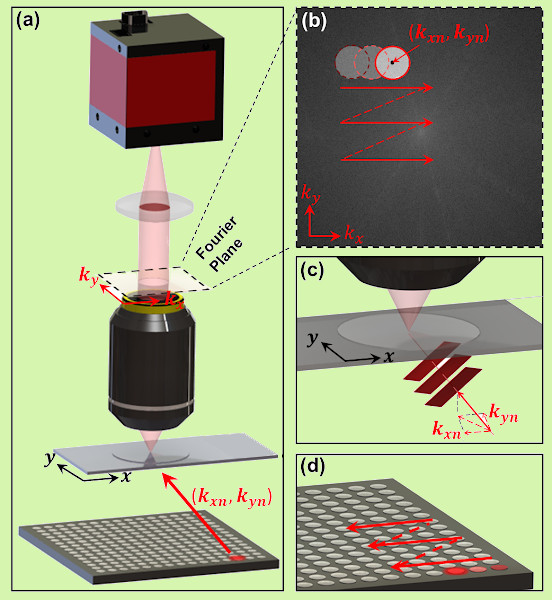
Image taken from the original FPM paper (linked in resources)
Above we see a sample being illuminated by a grid of LEDs one at a
time. In the top right, we see the locations in the image spectrum to
which those LED angles correspond. From here, we are essentially just
'stitching' together our low-resolution images in Fourier Space which
adds details at the different angles for us to Inverse Fourier
Transform at the end of the algorithm.
There are quite a few ways to build on this method; for example, there
is in fact an optimal order to add the images in and there is even
additional information we can retrieve by adding a few steps in the
middle of the procedure such as recovering pupil and chromatic
abberations of the lens we are using. We can even speed up the process
by illuminating the sample with multiple LEDs simultaneously in a way
which prevents interference in one anothers spectrum.
Our Final Results
By the end of the summer, my partner and I were able to successfully
construct a setup from 3D printed UC2 modules and program one of the
improved FPM methods.
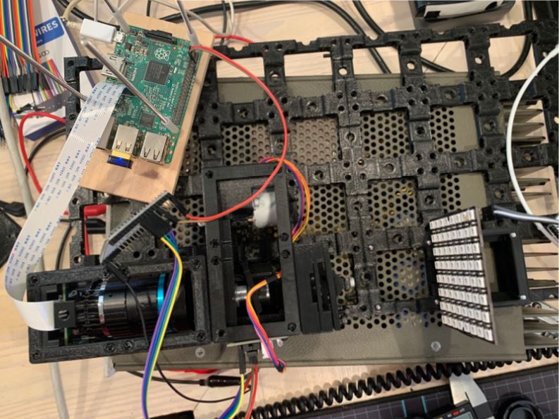
The finalized UC2 FPM setup
In our final setup we used a Raspberry Pi 3b and a High Quality
Raspberry Pi Camera. Some of the modules we needed did not exist
within the UC2 open standard yet so we needed to design them such as
one which would house the HQ RPI Camera and another which would shield
the sample from outside light.
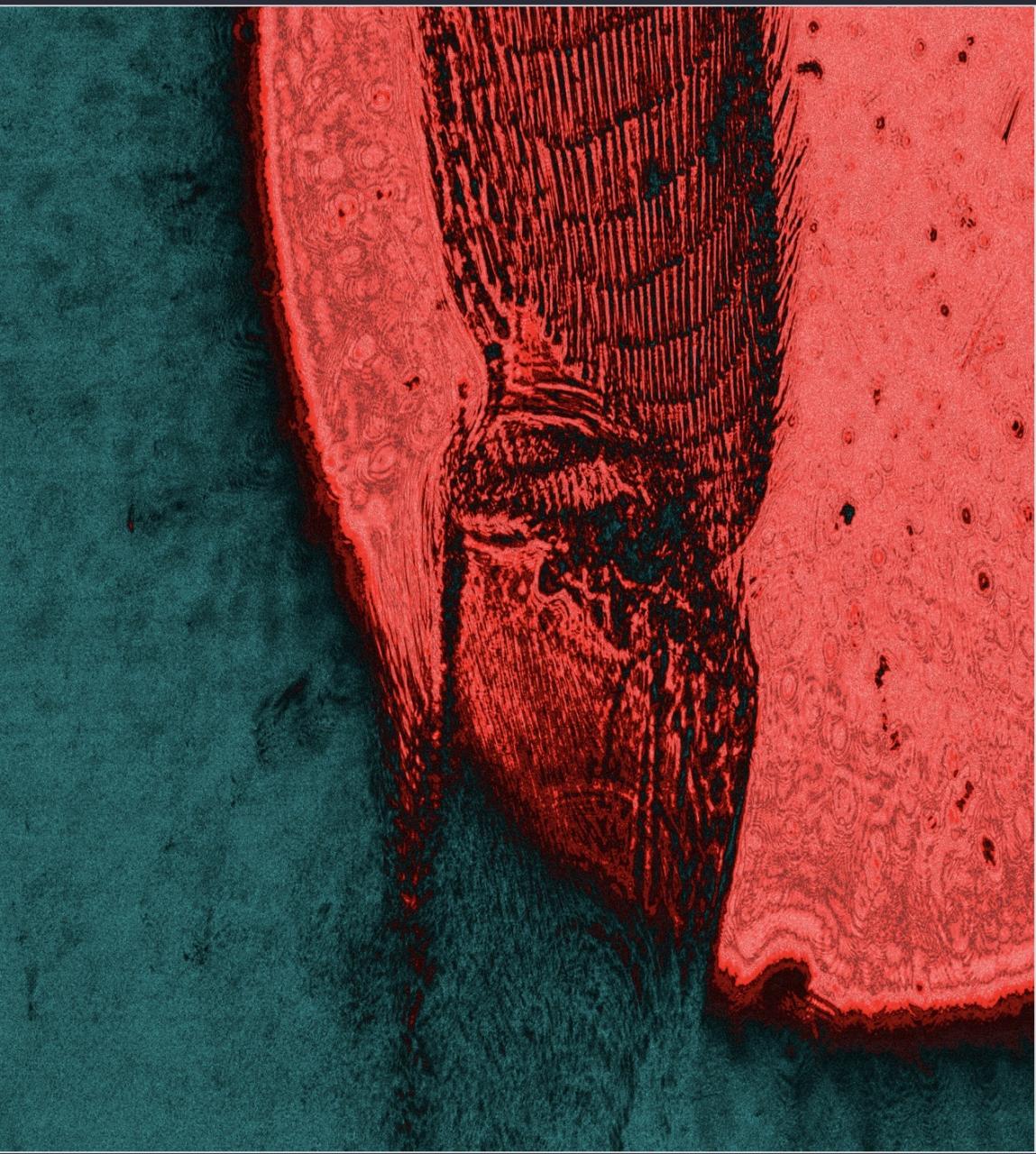
High-resolution image of a honeybee Leg produced with FPM
Finishing our design in the last few days of REU meant we didn't have
a ton of time to get images taken and processed, but this honeybee leg
shows that the system did in fact work.