Anatomy of QR Codes
3 min read
TLDR
(click to show/hide)
This article is really short, just read it.
We are surrounded by barcodes of all sorts that people usually don't
stop and think about. There's quite a bit of complexity behind matrix
barcodes like the QR (Quick Response) code that I'd like to spend a
bit of time breaking down to some degree. There is a lot of math
behind the error correction we'll leave out here (I want the main
takeaway to be the basic structure of these codes) but I found
this
amazing website that covers everything in extreme detail.
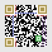
To start, here is an image of a QR code with the main regions
highlighted:
Gray: Quiet Zone, Yellow: Finder
Patterns, Green: Allignment Pattern,
Blue: Timing Patterns, Red: Format
Information, Purple: Data
Finder and Timing Patterns
Both the large finder patterns in the corners of the code and the
horizontal and vertical timing patterns serve to make the code more
readable by computer vision. These are relatively easy to consistently
find in an image and can then be used to evaluate the rest of the
grid. Another thing to notice is the lonely pixel by the bottom left
finder pattern. This is called the dark module and is
a square which is always black on all QR codes.
Format Information
The format information is written twice near the top left finder
pattern and broken in two along the other two finder patterns. The
format string is always 15 bits long. The first two bits describe the
error correction level 00 (M), 01 (L), 10 (H), and 11 (Q). The various
error correction levels have different data restoration capabilites. L
can restore approximately 7% of the data, M - 15%, Q - 25%, and H -
30%. These enable us to intentionally cover relatively large portions
of QR codes to make artistic renditions of them that will still scan
properly. The next three bits describe the mask pattern, the options
of which are listed below:
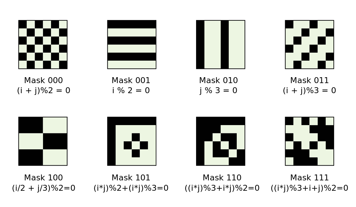
The eight unique masks used to XOR with QR codes
Masks work by taking the given pattern and duplicating it across the
entire code and XORing it with the data. They are used to break up
patterns which may be difficult to distinguish from finder patterns or
other important features of the code. The error correction level and
appropriate mask pattern are selected after looking at how the data is
laid out across the code.
Lastly, the ten bits following this information are the
Reed-Solomon Error Correction
bits. These deserve an entire article of their own since they require
quite a lot of math, but they enable the ability to have error
correction at all. Once the full format string is determined, it is
XORed with the final mask string 101010000010010 and written into the
two locations shown on the code.
Data
The data written into the QR code can be formatted in a few ways
including numeric mode, alphanumeric, byte, and kanji. The bytes used
to represent the string being encoded are snaked through the code in
the purple pattern shown above. Once these are laid out skipping over
allignment and timing patterns, the mask is applied and we are
basically done.
Version and Allignment Patterns
QR Codes have version numbers ranging from 1 to 40. Version 1 codes
are 21x21 and the size will increase by 4 in each direction with each
subsequent version. This means that version 40 codes are 177x177! As
the size of these codes increase, it can be more and more difficult
for a scanner to locate the finder patterns. To solve this, starting
with version 2 codes, allignment patterns are added to make the code
more manageable.
Resources
Apologies for the relatively short article this week! School has just
started meaning all of my extracurriculars have as well. Hopefully you
still learned a bit from this. Stay tuned for the cool article I have
planned for next time though!